Join parts with connectors
Connectors describe where reusable parts can meet. They are ordinary operations in the MZ recipe, not separate actions for individual assets. A connector has a family, a local position and an outward-facing rotation. It adds no visible geometry.
Two connectors can join when their family keys match and their outward directions oppose each other. For example, a straight wall's right end can meet another wall's left end, a corner's end, or a doorway jamb module's end.
Prepare the building parts
- Use a flat area in a 2D Iso map.
- Create Wall segment, Wall corner and Doorway through the recipe browser.
- Keep wall heights and thicknesses consistent. The default wall height is 2.4.
- In the compact placement sidebar, enable Follow recipe shape and Snap connectors.
- Set Top height to zero, disable Fill below, and keep Walkable top off for the walls.
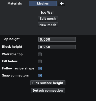
Selecting a mesh keeps the map visible. Open Edit mesh only when changing its recipe.
Build a small room
Place one wall corner as the starting part. Its two arms extend along local X+ and Z+.
Select a wall segment and click near an arm's free endpoint. The placement searches compatible connectors within 0.8 world units of its tentative placement. It can choose a baked orientation to align the join. The connector positions coincide exactly even when the grid cell center is only an approximation.
Continue placing wall segments at the free end. Rotate the brush with R when preparing the next corner. The selected brush orientation wins when equally good joins exist. Place a doorway along one wall, then continue with wall segments on the other side. Walk through the opening to verify its compound footprint.
The last piece can close the room geometrically. The saved links form a parent chain rather than a cyclic constraint network: the closing join does not add a second parent link. When you change the dimensions of a completed loop, check its closing seam and re-place or adjust that end if needed.
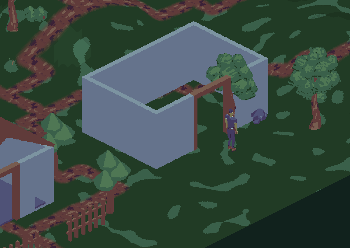
The playground includes a separate connector exercise. Each wall or corner remains a reusable asset.
Change a dimension
Open the wall recipe and change its width. Its end connectors move with the Box width. Connected children follow their parent's new connector positions, and their footprints update afterward. A sequence of joined parts therefore follows a size change without matching coordinates manually.
This is a shared recipe edit: every placement using that recipe changes. Use a separate recipe copy for a wall that needs an independent width. Connector links do not solve contradictory dimensions around a closed loop or stretch neighboring assets to fill a gap.
Add a roof or floor
Walls and doorways expose an upward roof connector at their top. Gable roof has an opposing connector at its base. Set the intended placement height close to the wall top before placing it; snapping searches nearby heights as well as horizontal positions. For a default wall, start at Top height 2.4. The roof then follows the connected wall's placement height and its recipe-defined roof seat.
The Box recipe also exposes four floor edge connectors. You can use a thin box as a reusable floor module. Its connectors sit at the box's top height in local coordinates. A custom slab whose top is local Y=0 should put its connectors at Y=0 as well.
A roof connector defines alignment, not an automatic roof-fitting rule for an entire room. Publish and bind the roof's span/depth to the dimensions you intend to use.
Author a connector in MZ
- Open a mesh Group and add Sources → Geometry → Connector after the mesh construction.
- Set Position X/Y/Z in the mesh's local coordinates.
- Set its rotation so local +Z points out of the joining face.
- Select the Tile tab. In the operation's source text, enter its family key, such as
wall, then click Apply. - Publish bindings for every connector coordinate that depends on a variable dimension.
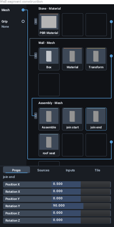
The Tile source editor edits only the connector family for this operation. Family keys are case-sensitive and accept 1–64 ASCII letters, digits, _, -, . or /.
Useful rotations for an untransformed connector are:
| Outward direction | Rotation X/Y/Z in degrees |
|---|---|
| +Z | 0, 0, 0 |
| -Z | 0, 180, 0 |
| +X | 0, 90, 0 |
| -X | 0, -90, 0 |
| Up (+Y) | -90, 0, 0 |
| Down (-Y) | 90, 0, 0 |
A width-centered straight wall uses positions [-width / 2, 0, 0] and [width / 2, 0, 0] with outward directions -X and +X. Bind the connector X positions to width with multipliers -0.5 and 0.5. A roof seat at [0, height, 0] binds Y to wall height.
Transforms carry positions and directions with the mesh. Whole-group transforms do the same. Repeat copies connectors with distinct stable IDs; Assemble retains connectors from its input rows. Up to 256 connectors are supported per evaluated mesh.
Detach and troubleshoot
Select a connected placement and click Detach connection to freeze it at its current position. Its collision footprint can still follow the recipe. Turning Snap connectors off affects future placement; it does not detach existing links. Rotating a selected part with R detaches its incoming link before changing its orientation.
Occupied connector endpoints are excluded from new joins. Missing parents or renamed/removed connector identities leave the affected placement in place rather than moving it unpredictably. Links survive save/reopen and participate in the placement stroke's undo. Copying connected parts together preserves their internal links; copying a child without its parent detaches that incoming connection.
Snapping currently operates in the 2D Iso Rect mesh placement workflow. It uses the cached static directional views, so sprites, collision shapes and connectors agree. It does not attach animated actors, deform rigid building parts over terrain, or establish multiple simultaneous constraints on one part.