Working with Geometry
Creating geometry is crucial for both 2D and 3D maps. We have 3 different types of geometry in Eldiron:
- Vertices are points in the map.
- Linedefs are lines between the points.
- Sectors are a series of linedefs which form a closed polygon.
The terms Linedefs and Sectors are based on the game Doom, which used the same terminology.
You can apply tiles only to sectors, for example via the Apply Tile button in the Tile Picker dock or by using the Rect tool.
Creating Sectors
To create a sector we use the Linedef tool.
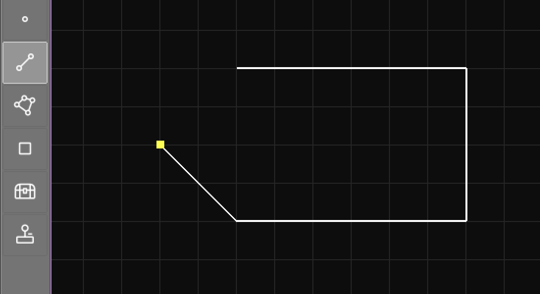
When you click on grid positions, the Linedef tool automatically creates new vertices and linedefs between those points. Clicking the starting vertex again closes the polygon.
Here we selected the Sector tool to select the newly created sector.
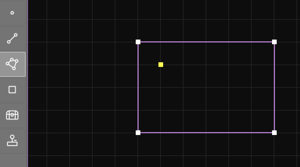
By default the linedef tool is in manual mode, meaning you have to click every vertex position to create a sector, even if some of the vertices already exist.
When you hold Cmd/Ctrl while clicking the tool tries to auto-close existing polygons on every click, so you just need to click on the vertices you want to connect to close a polygon.
Applying a Tile
Now we can apply a tile to the sector using the Apply Tile button in the Tile Picker dock. It applies the currently selected tile in the tile picker to the currently selected sector.
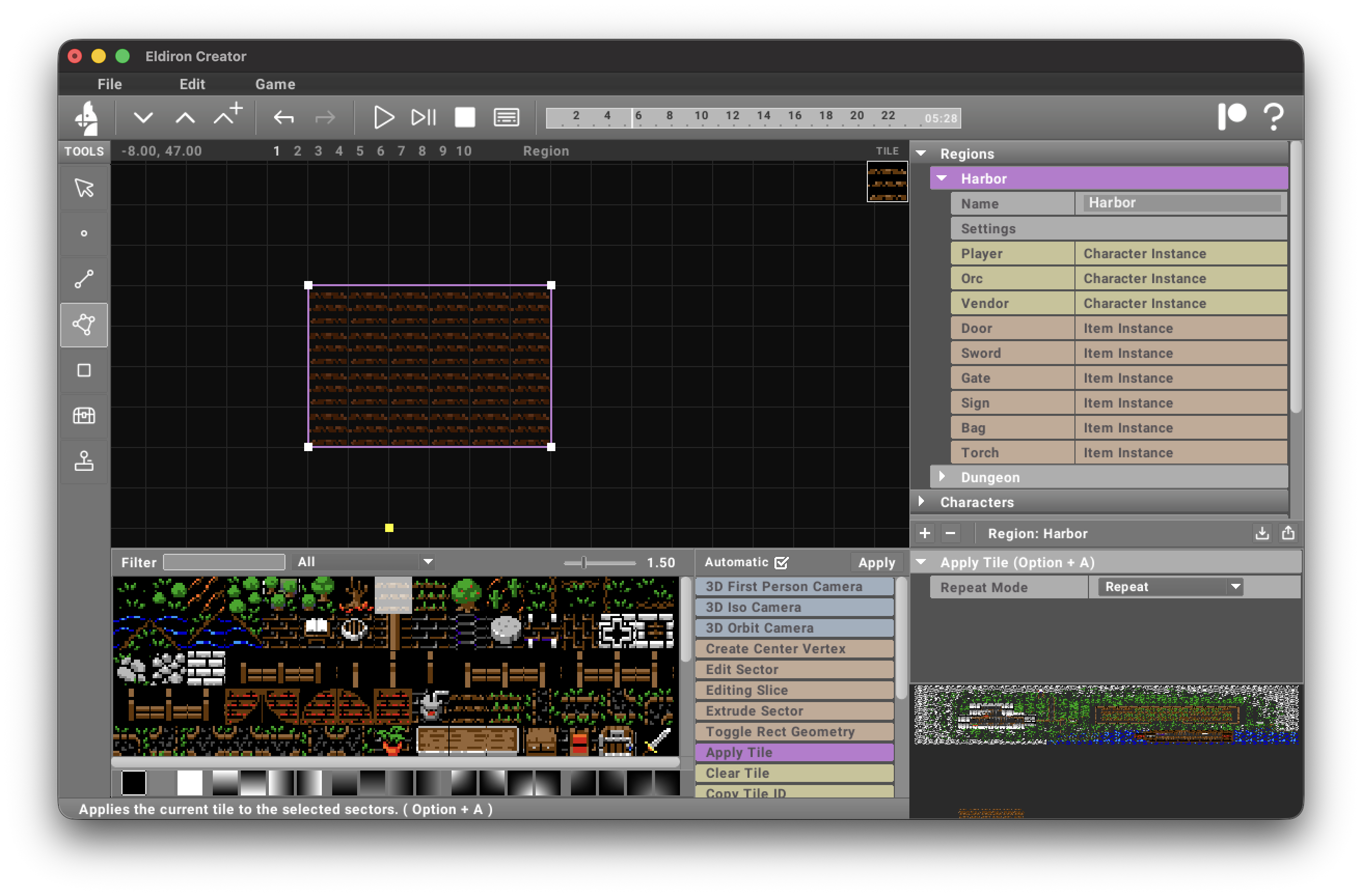
The Rect tool does all the above in one step, it creates a rectangular sector and applies the currently selected tile to it, but it is only used for decoration purposes (i.e. quickly drawing tiles). When you want to create the foundations of an area (for example a house), you need to create its sector manually.
Other Functions
The Vertex, Linedef and Sector tools have a diverse set of functionality, so make sure to read their documentation. You can, for example, create new standalone vertices with the vertex tool by holding Shift and clicking in the grid.
3D Geometry Modes
In 3D views, Eldiron uses direct Geometry Object editing.
The same tool names are reused, but they operate on the selected 3D object:
- The Object Tool selects and transforms whole objects.
- The Vertex Tool selects and edits object vertices.
- The Linedef / Edge Tool selects and edits object edges, and draws surface lines on selected faces.
- The Sector / Face Tool selects and edits object faces.
This keeps the 2D editor vocabulary intact while giving the 3D path direct object, face, edge, and vertex editing.
The 3D editor works with Geometry Objects. Existing 2D linedefs are shown as a faint floor-plane reference overlay, and the 2D map data can still be used for gameplay zones, triggers, and minimaps.
Surface lines are the 3D path for drawn detail. Draw them on a selected face with the Linedef / Edge Tool, then use actions such as Create Ridge, Create Groove, or Create Cutout to turn those lines into persistent geometry or through-object openings.
Press Delete to remove the currently selected geometry.
All geometry editing operations are undoable.
Construction patterns
The Wall Tool creates and selects walls, floors, and ceilings. Its panel switches between Build, Select, Opening, Brick, and Surface modes. In Surface mode, choose Floor or Ceiling and click inside a closed wall loop to fill it, or Shift-drag a rectangle anywhere to create an independent surface. Floor and ceiling visibility can be toggled in the editor without changing game visibility. Choose Floor or Ceiling, then Fill All to detect enclosed areas, including short aligned doorway gaps, and highlight their outlines. Review the outlines, then click Create All to create only that surface type, or press Esc to cancel. Newly created surfaces receive an editable Surface branch with subdivision and material nodes. Matching surfaces created in one bulk operation share the branch; different ceiling heights retain separate branches. New surfaces use a gray Noise → Gradient material by default. Choose Value or Voronoi on Noise and adjust scale and seed. Connect its Value output to Gradient’s left input; Gradient maps the field between its two color parameters (choose each from the artist palette) and sends Material from its right output to the surface or pattern. Noise tiles repeat seamlessly and are generated into the texture atlas. Bulk ceilings use the tallest boundary wall; adjoining ceilings at different heights generate vertical closures along their shared edges. Shorter boundary walls also receive closures up to the ceiling, so varying wall heights leave no gaps. Existing surfaces retain their authored elevations; adjust their Surface branch or recreate them to use the new inferred height. Hide Ceilings clears the editing view without removing them.
The Construction dock uses the same branch workflow as Behavior Nodes: branches appear to the left of the graph, and available nodes appear in the sidebar's Node List. Drag a Wall, Surface, or Pattern root from Node List into the graph to create a branch. Click a branch to edit it; use Assign to Selection to link a Wall or Surface branch to the selected geometry. The filled dot marks the assigned branch. Branches are project-wide and can be shared by multiple walls or surfaces. Floor and ceiling use the same Surface branch type. The Construction toolbar's Tidy Graph button lays out the selected branch left to right; adding, removing, or reconnecting nodes tidies it automatically. Moving a node manually does not. The Fill slider beside the editor camera buttons brightens the 3D editing preview without changing the game's lighting.
Surface graphs use Surface, Inset, Subdivide, Pattern Reference, Color, Tile, and Surface Output. Connect geometry terminals to the geometry input, and material terminals to the output's Top or Sides input. Different terminal types cannot be connected. The Inset value controls the gap around the area; Subdivide adds a shallow repeating quad pattern to rectangular areas. The Surface node controls elevation and thickness, and the output controls material repeats. Click a Color or Tile field to choose visually from the project's palette or authored tiles. When a Wall or Surface branch is assigned, its graph owns the material slots marked N in the top material strip. Edit those materials in the branch. Opening surrounds and the older assembly floor slot remain independent material overrides. To use a shared Pattern on a floor or ceiling, put Pattern Reference in the geometry chain between Surface and Surface Output, then choose a Pattern branch. Its block width and height become the two surface subdivision axes; its stone and mortar materials become the top and grout. An explicit Color or Tile connection to Surface Output's Top or Sides input overrides the shared material for that face. Disconnect the default Top color connection to see the Pattern's material. Wall branches run left to right: Wall sets basic dimensions, its Build output connects to a Pattern Reference, and that connects to Wall Output. A reusable Pattern branch runs Pattern → Masonry → Wall Finish → Pattern Output. Color and Tile nodes feed the Stone, Mortar, and Frame material inputs. Rearrange, replace, or bypass the middle geometry nodes to change what the branch builds. The reference selects a shared Pattern branch; editing it updates every wall that uses it. This is the initial modular node set, with room for more geometry and material operations. Insert Pattern Scale into the Build chain to multiply block width and height. Connect several Color or Tile nodes to Masonry's Stone input to vary the stones; the Stone Variation setting in Wall Finish controls how often alternate materials appear. The same Pattern branch can be used by Wall and Surface branches, so edits to it refresh both. The present renderer supports block subdivision and material variation on rectangular surfaces; further geometry operations will need corresponding renderer support.
For Stonefall, open the Wall Tool, choose SURF → Floor, and click Fill All. Check the highlighted areas before clicking Create All. Repeat with Ceiling selected to add ceilings. The detection gaps are temporary; it does not add wall spans. Click a created surface to select it and assign a shared Surface branch in the Construction dock. Use Hide Ceilings while editing below them; this affects only the editor preview. Individual surfaces can still be added with a click or Shift-drag. Geometry retains its last valid appearance while a pattern graph is incomplete.
Branches are arranged on their first opening. After that, node and connection edits preserve your layout. Use Tidy Graph to arrange them again explicitly. Newly created construction graphs start with a left-to-right layout.